Project 3 - Volume Rendering and Transfer Functions


Key Dates
Handed out: October 12, 2015
Due: October 26, 2015 at 8:00 am
Objective
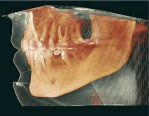
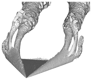
The topic of the third assignment is volume visualization through direct volume rendering. You will experiment with transfer function design and revisit some of the tasks of the second assignment to compare the effectiveness of isosurfacing and volume rendering in two application scenarios. Specifically, you will apply volume rendering to a medical dataset (same CT volume as in the previous assignment) and to a computational fluid dynamics (CFD) simulation of a delta wing aircraft in a critical flight configuration.
Background
The key to achieving good results with volume rendering is to select an effective transfer function. We saw in class that a good transfer function should reveal boundaries present in the volume, when such boundaries exist. When clear boundaries are not present, the transfer function should be designed to reveal important geometric structures in the data. In this assignment, you will be working with two datasets that illustrate these two scenarios: the CT dataset contains boundaries corresponding to the interface between different tissue types while the CFD dataset describes the spatial distribution of vorticity in a fluid flow and is globally smooth. The project starts by asking you to identify remarkable (iso)values in each dataset, which you will then use as reference points to create your transfer function. The third part of the project invites you to compare the respective pros and cons of volume rendering and isosurfacing in the context of these two datasets.
Tasks
Task 1: Salient Isovalues
Your first task consists in determining for each dataset a set of isovalues that capture salient (remarkable) structures in the considered field. To do so you will use the code that you wrote for the third assignment to identify important isosurfaces. In the case of the head dataset, salient isosurfaces capture boundaries corresponding to the skin, muscles, skull, and teeth (you saw that the brain is an elusive structure in this dataset). In the case of the delta wing dataset, you will look for isosurfaces that reveal the vortices present on both sides of the wing and in particular the various layers that compose these vortices. Other key features in this dataset are so-called recirculation bubbles that are present on each side of the trailing edge of the wing. Bear in mind that fuzzy structures might be poorly captured by isovalues. Using different opacities for different isosurfaces, create for each dataset a visualization showing all isosurfaces simultaneously.
Deliverables: Create two executables for this task: salient_ct[.py] and salient_cfd[.py] that each contain the (hardcoded) information needed to visualize the salient isosurfaces of the corresponding dataset using transparency. In both cases, your executable will receive the name of the file to visualize from the command line (which allows me to specify an arbitrary location and resolution for the input file).
> salient_ct <head.vtk>
> salient_cfd <cfd.vtk>
Report: Describe in the report how you selected isovalues for each dataset. Include pictures showing each isosurface individually and other images showing all isosurfaces combined using transparency. Make sure to use the same camera setting across all images corresponding to the same dataset.
Task 2: Transfer Function Design
Once you have found good isovalues, you will design a transfer function for each dataset based upon those values. For that, create a vtkVolumeProperty by following the example provided in Examples/VolumeRendering/Python/SimpleRayCast.py to define both color and opacity transfer functions in order to emphasize the selected isovalues. You are already familiar with vtkColorTransferFunctions from previous assignments. The opacity transfer function is defined through a vtkPiecewiseFunction. Your objective in designing the opacity transfer function is to reveal as much as possible of the internal structures of each dataset. The volume rendering itself will be performed by raycasting using a vtkVolumeRayCastMapper. Note that this implementation is rather slow but produces very good results. In addition, it takes advantage of the parallelism available on your machine to speed up the computation. Use vtkVolumeRayCastCompositeFunction for value compositing along each ray. Your implementation should produce high-quality renderings by combining trilinear interpolation and small sampling distance along each ray: you will select SetInterpolationTypeToLinear() in the API of vtkVolumeProperty and manipulate the discretization along each ray via SetSampleDistance(). You will need to experiment with different values of the sampling distance to determine the precision necessary to obtain good results. Good results in particular should not exhibit aliasing artifacts such as moiré effect. Note that an appropriate value of the sampling distance depends both on the smoothness of the data and on the properties of your transfer function. Finally, you should activate the shading option (via ShadeOn() in vtkVolumeProperty()) in your rendering to further improve the visual quality of your results.
Deliverables: create two executables dvr_ct[.py] and dvr_cfd[.py] that contain the information necessary to create high quality renderings of the corresponding dataset. In particular, the opacity and color transfer functions must be hard coded in these programs. As for the first task, your executables must obtain the name of the data file from the command line.
> dvr_ct <head.vtk>
> dvr_cfd <cfd.vtk>
Report: Provide a detailed description (including diagram) of the various transfer functions you created along with a justification of the choices made. What method did you use to create each opacity transfer function? What do you consider to be the strengths and limitations of your solutions? Include in the report several images for each dataset that highlight the effectiveness of your transfer function and the quality of your volume rendering parameters.
Task 3: Volume Rendering vs. Isosurfacing
Provide for each dataset a side by side comparison between the results obtained for isosurfacing (Task 1) and volume rendering (Task 2). Make sure to use the same camera settings for both techniques in order to facilitate their comparison. No additional code should be written for this task: simply use the executables created for the previous tasks to create the images that will be included in the report.
Report: Comment on the differences between the two techniques. Illustrate your argumentation by zooming on particular features of each volume. For each dataset, which technique do you find most effective? Why? Be specific.
Summary Analysis
Include in the report your critical assessment of volume rendering: What are in your opinion the pros and cons of this technique? Refer to the tasks of this project to justify your opinion.
Data Set
You will be visualizing two datasets for this assignment. The first one is the head CT dataset that you used for Project 2 (see comment below). The second dataset corresponds to a computational fluid dynamics simulation of a delta wing aircraft in a critical flight configuration (low speed and high angle of attack). In this case the provided scalar volume corresponds to the magnitude of the vorticity field, a quantity that is derived from the flow velocity and can be used to identify vortices in numerical datasets.
Note that both datasets have been low-pass filtered (“smoothed”) to facilitate their visualization (e.g., reduce aliasing issues). In particular, the CT dataset in this project is smoother than the one you used previously.
The datasets are available online. All datasets are of type vtkStructuredPoints.
-
Visible Female Head:
-
CT scan, low resolution (
unsigned char, 8.1MB) -
CT scan, high-resolution (
unsigned char, 64MB)
-
CT scan, low resolution (
-
CFD Dataset:
-
Vorticity magnitude (
unsigned short, 18MB)
-
Vorticity magnitude (
Submission
Submit your solution for this project before October 26, 2015 at 8:00 am. Refer to the instructions below.
- Include all program files (
salient_ct,salient_cfd,dvr_ct,dvr_cfd) along with any other source code you may have. - Include
Makefile(resp.CMakeLists.txt) (if applicable). If you are using Visual Studio include the solution file (.sln) and the project files (.vcproj) that are needed to build your project. - Include high resolution sample images showing results for each task.
- Include a html or PDF report briefly summarizing what you have done and answering all the questions asked. As always, the report should include high-resolution images.
- Include
README.txtfile with compilation / execution instructions (optional). - Include all submitted files in a single directory named
<myLogin>_p3, where<myLogin>is your Purdue login. - Do not include binary file
- Do not include data files
- Do not use absolute paths in your code
After logging into data.cs.purdue.edu, submit your assignment as follows:
> turnin -c cs530 -p project3 <dir_name>
where <dir_name> is the name of the directory containing all your submission material.
Keep in mind that old submissions are overwritten by new ones whenever you execute this command. You can verify the contents of your submission by executing the following command:
> turnin -v -c cs530 -p project3
Do not forget the -v flag here, as otherwise your submission would be replaced by an empty one.