CS250 Lab 2
Implementing a Circuit that Computes
Even Parity
Goal
In this lab you will learn how to use the protoboard and you will
build your first hardware experiment.
1. The Protoboard
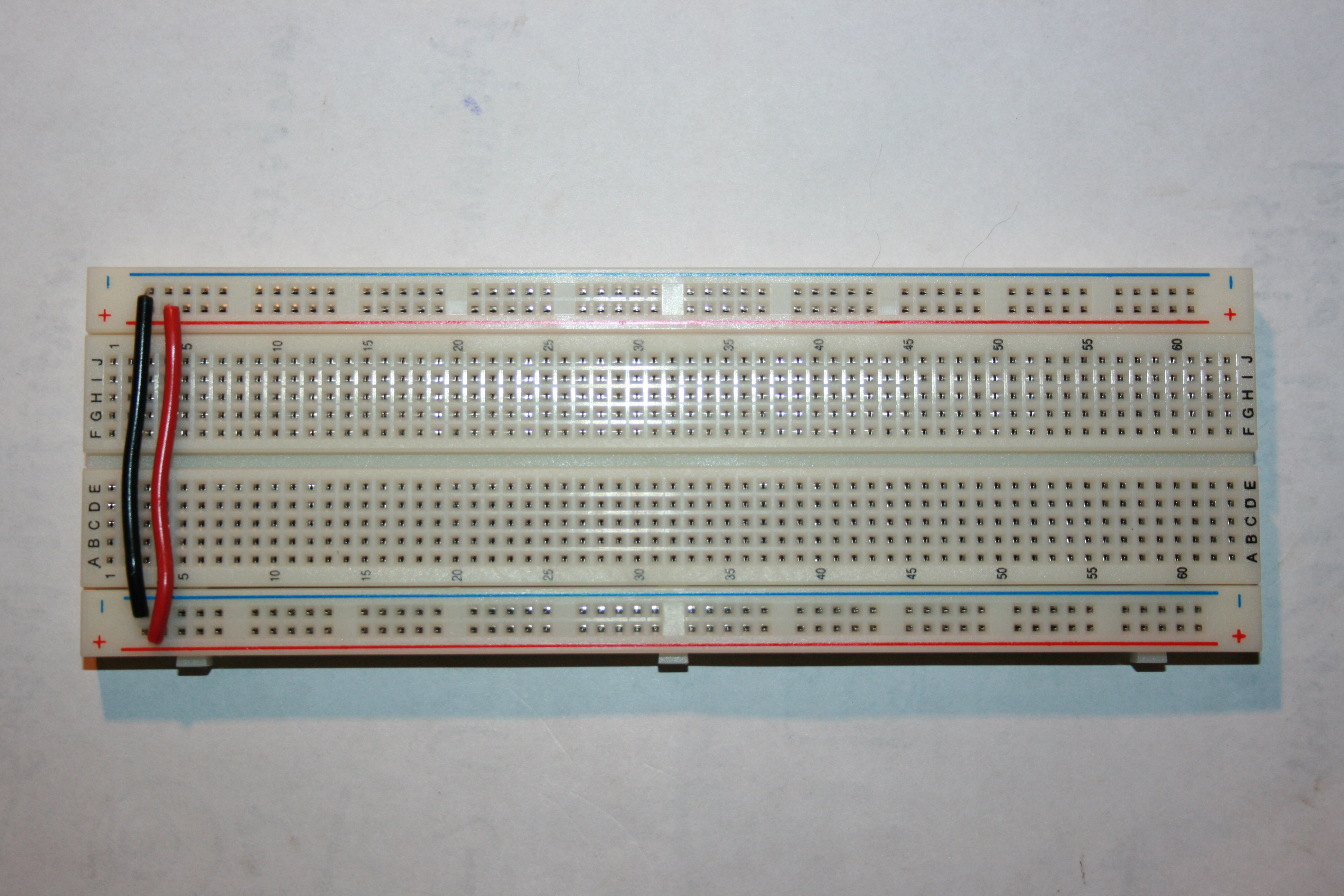
The protoboard or breadboard is a base made of a matrix of
sockets used to build temporal electronic circuits. Here is the
picture of the protoboard you will use in this lab.
")
In the protoboard the 2 top and 2 bottom rows are used for the
power. The columns in the middle are connected according to the
following picture.

2.Connecting to the Power Supply of the Arduino
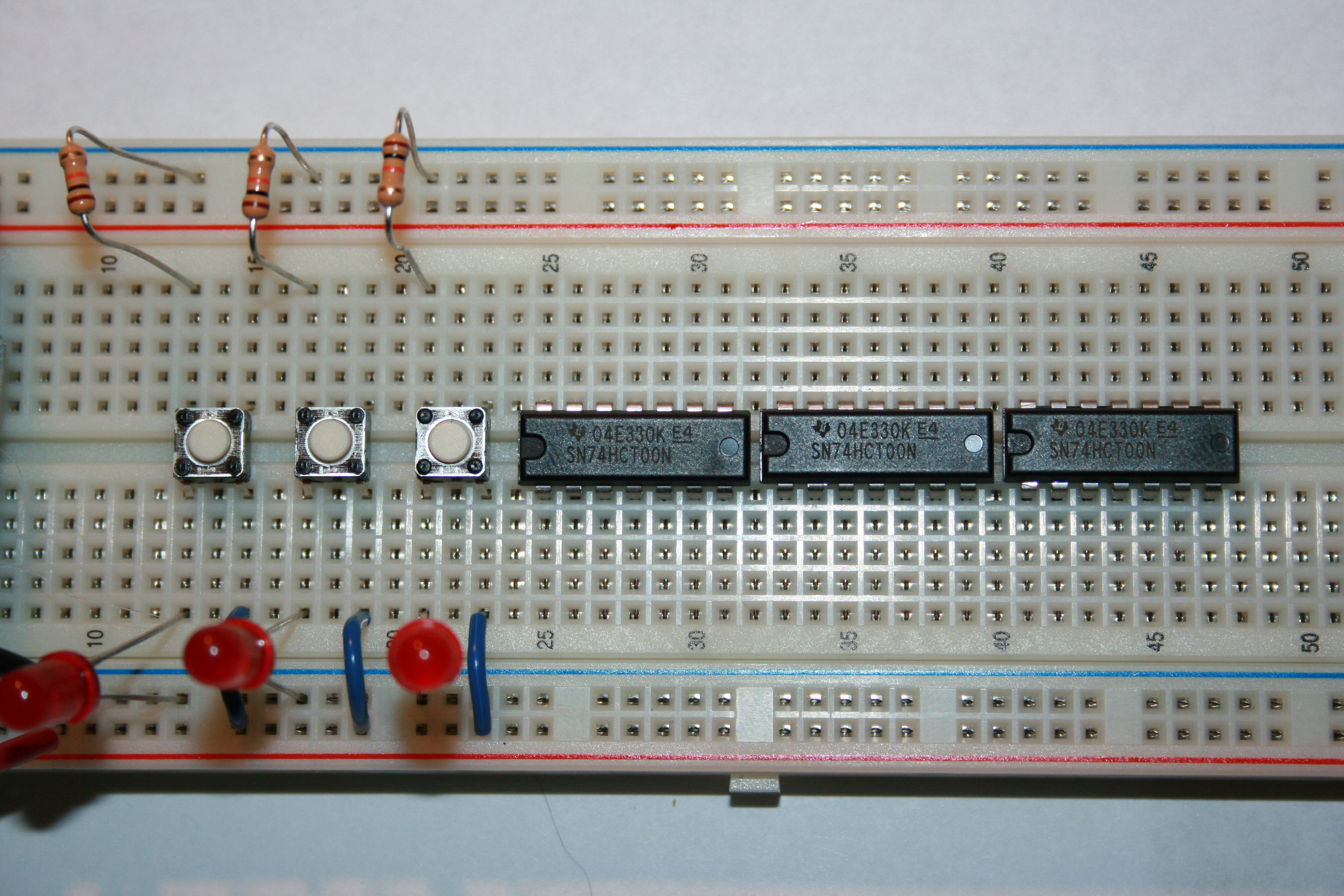
We recommend that you place the different components first before
doing all the wiring. Placing the components in the places suggested
in the picture will make it easier to debug and get help from the
instructors.The kit includes wire of different colors. You will use
the wire strippers provided in the lab to cut the wires and remove
the plastic from the conductor. Leave about 1/4 inch of coductor in
each side.
Use the cutter at the base of the pliers to cut the wire. To strip
the plastic from the conductor select the 22AWG knob in the tool and
press the wire with the hole at the top of the tool. Rotate the tool
around the wire to cut the plastic and then pull out toward the end
of the wire. If you need to put too much force to pull the plastic
out, try rotating the tool 360% to cut the plastic first.


The Arduino board you received in your kit will also work as the
power supply of your digital circuits. Unwrap the Arduino and use
the Arduino's box to store the speaker. The speaker cone is made of
a plastic material called Mylar that can break easily.
First connect the top positive red row with the bottom positive red
row. Then connect the top negative black row with the negative
bottom black row. As indicated in the picture.
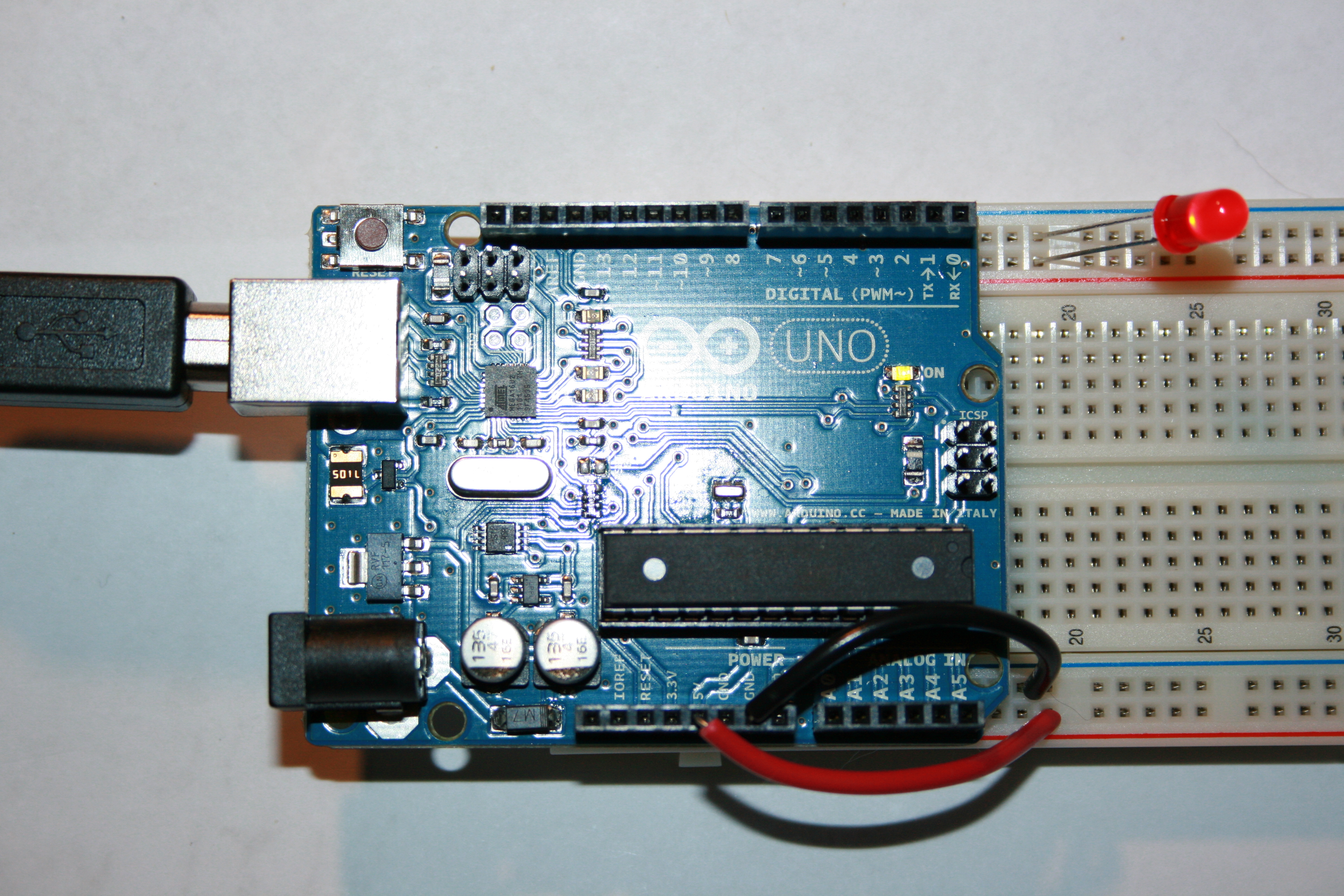
Place the unconnected Arduino in the left side of the protoboard and
connect a red wire from the 5V terminal in the Arduino to the red
row in the breadboard. Also connnect a blacwire from one of the GND
terminals in the Arduino to the blue row in the breadboard. Now also
connect a LED as indicated in the picture. The longer terminal in
the LED has to be connected to +5V (red row) and the shorter
terminal to GND (blue row). Once you connect the Arduino to the
computer using the USB cbale, the LED should light up.
3. Implementing the XOR Function Using Nand Gates
You will implent the XOR function using only NAND gates. The truth
table of the XOR function is the following:
x
|
y
|
x XOR y
|
0
|
0
|
0
|
0
|
1
|
1
|
1
|
0
|
1
|
1
|
1
|
0
|
Using the 1s in the truth table we can build the XOR as
x
XOR
y
= xy'+x'y
where x' means NOT x.
Now if you negate twice the right side and applying De Morgans law.
x XOR y = ((xy'+x'y)')' = ((xy')'(x'y)')' = (x NAND y') NAND (x'
NAND y)
Also, since x'= (x x)' = x NAND x and y' = y NAND y then we have:
x XOR y = (x NAND (y NAND y)) NAND ((x NAND x) NAND y)
We can implement the XOR using only NAND gates as follows:

4. Implementing the Circuit in a Breadboard
Disconnect the USB cable from the Arduino before continuing building
the circuit.
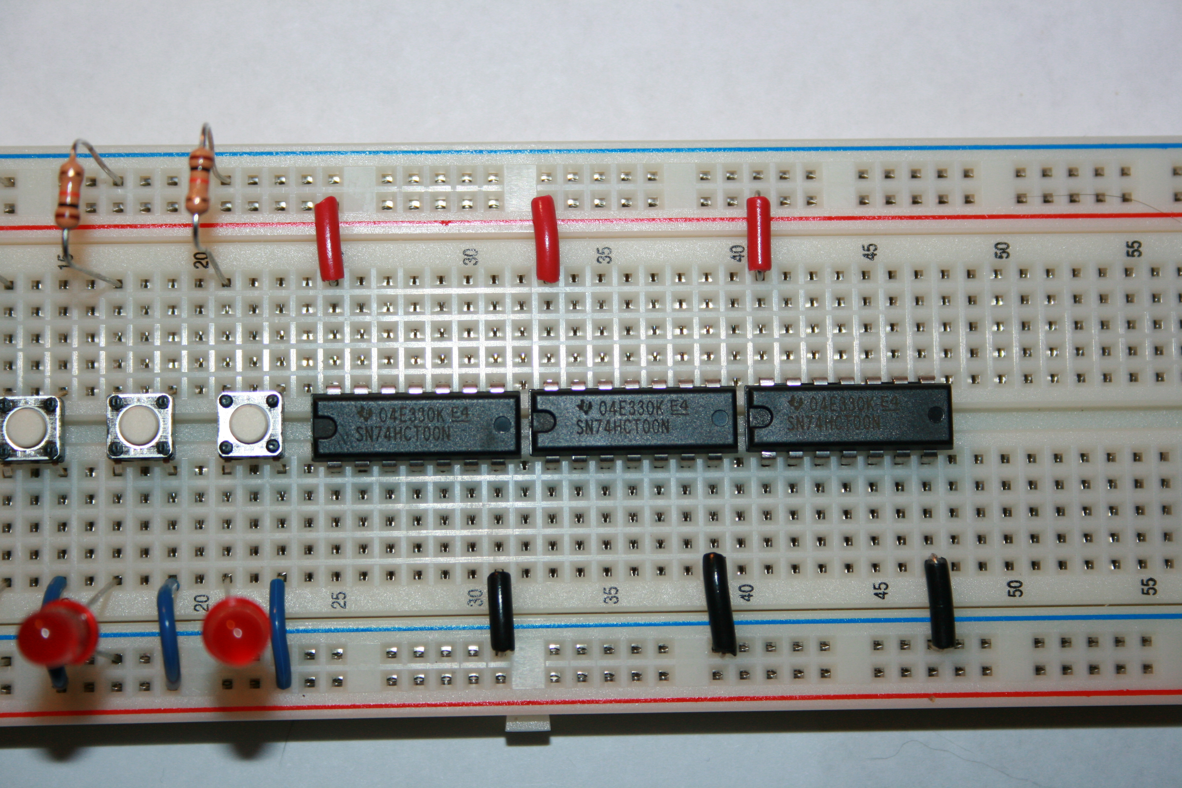
In Binary logic a true value or 1 is represented as 5V and a false
value or 0 is represented as 0V. Notice that the push button when
not pressed gives a 0 V or 0 through the 10K resistor, and when
pressed they give +5V or 1. Build the following input circuit with
the buttons as shown in the picture.
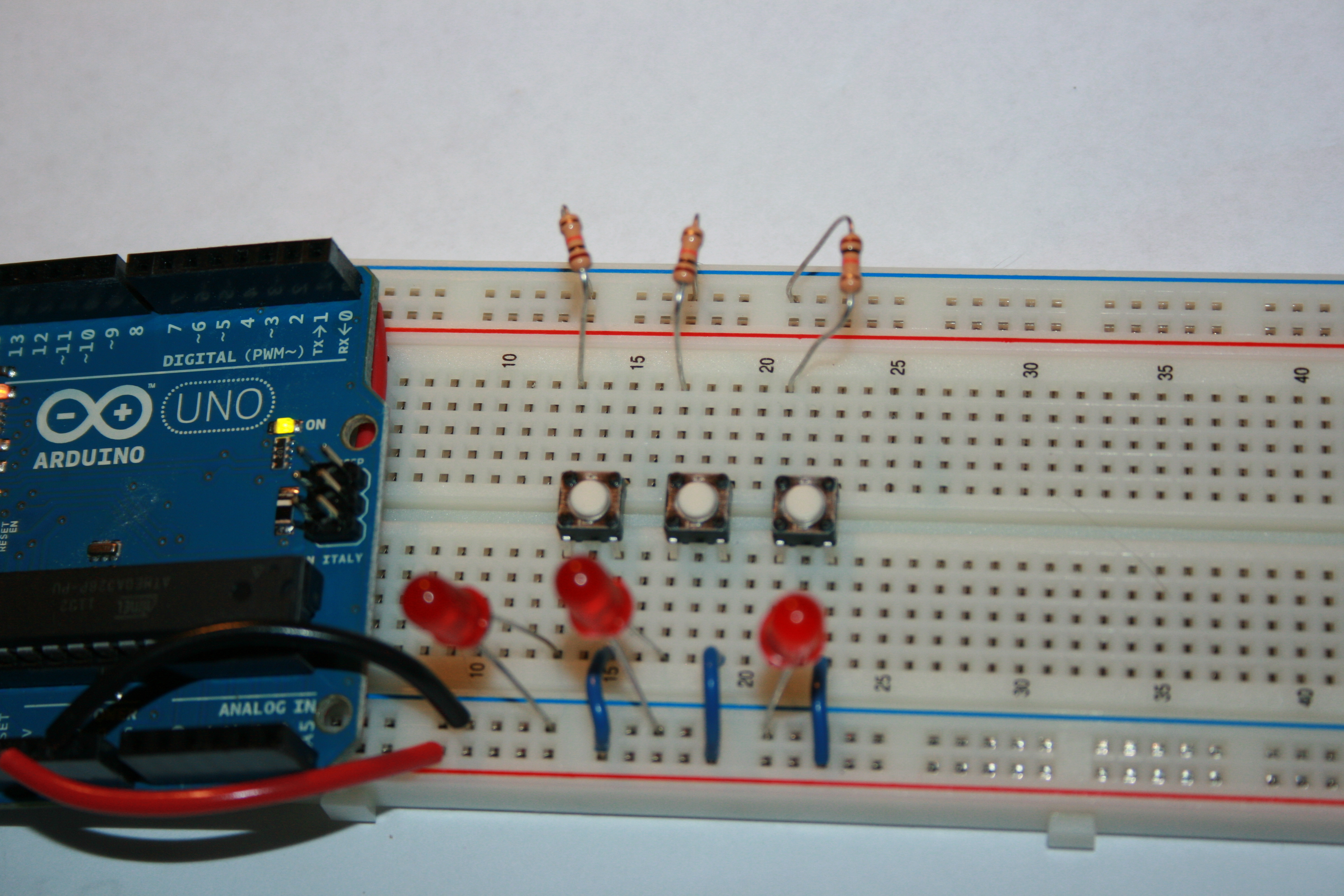
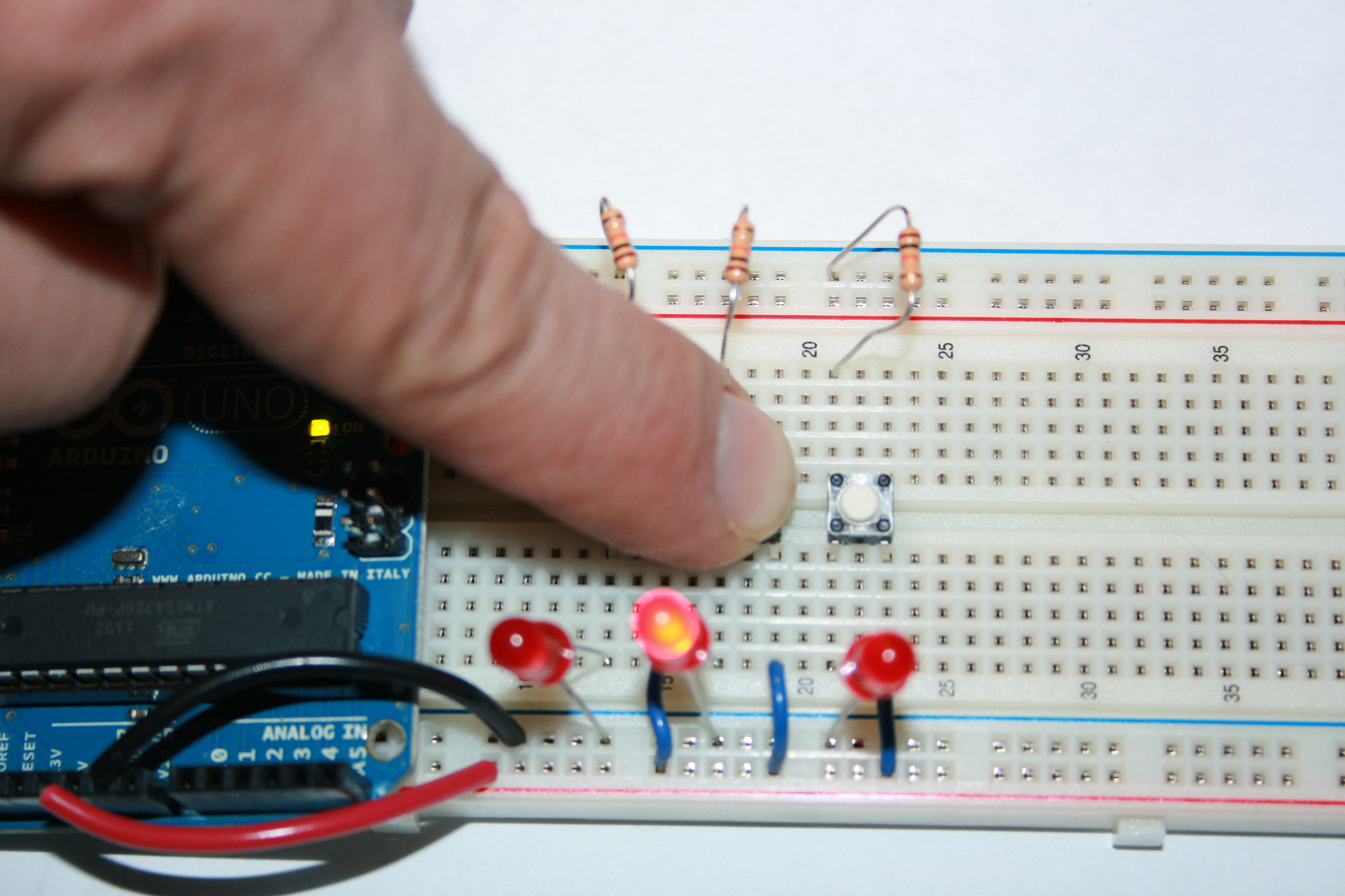
Now press the buttons to test that the corresponding LED lights up.
Remember that the shortes terminal of the LED goes to GND (blue row
in the breadboard).
After this, connect the NAND gate chips SN74HCT00N as shown in the
picture. It might be difficut to read the labels in each chip so
read the labels carefully. Notice that the dent in each chip is
placed in the left. The little bubble in the left-bottom corner
indicates the pin number 1. The datasheets for the chip is located
in
Here is the pin assignment for the SN74HCT00N .

Connect the power for each chip. Pin 7 is connected to ground (-)
and Pin 14 is connected to +5V. It is standard to use black wire for
(-) and red wire for (+).
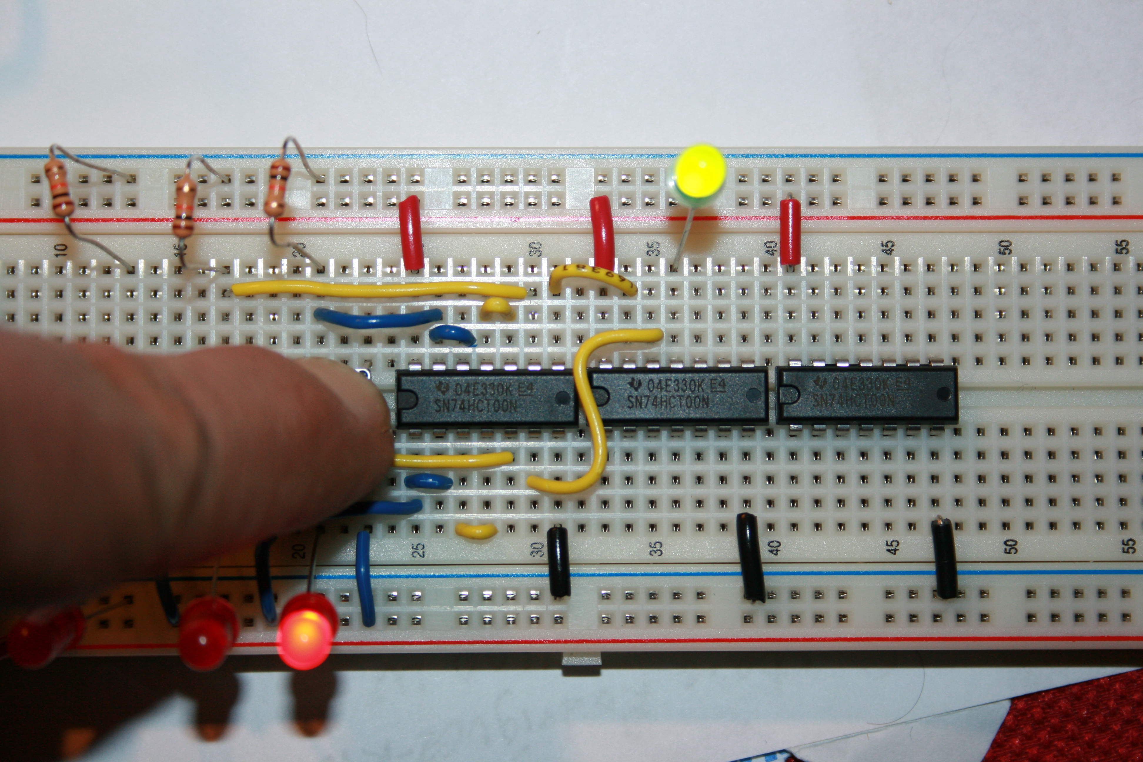
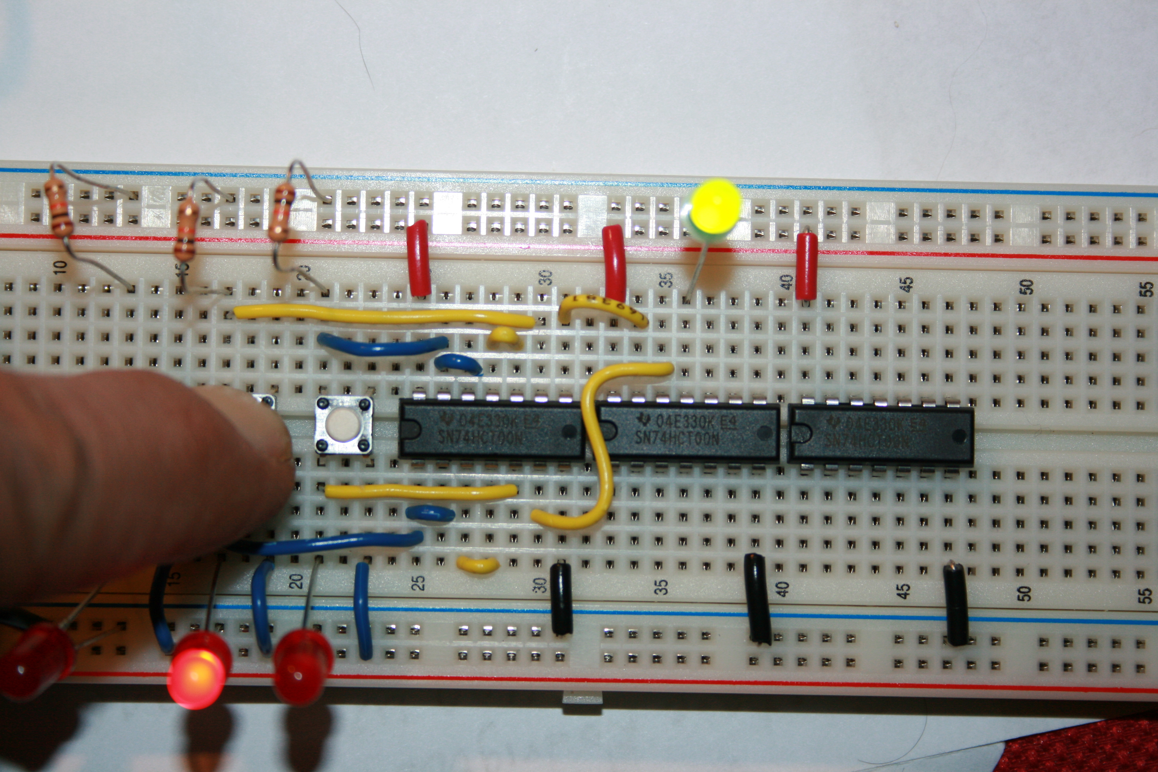
You will only use the two rightmost buttons for the inputs of y and
x. The leftmost button will be "z" and you will use it later. Now
connect the gates to implement the XOR as indicated in the pictures.

Make sure that by pressing the x and y buttons you obtain the
expoected results for an XOR.
Implement an Even Parity
Function To Bring to Your Next Lab
Parity is used in communications to check if a sequence of bits is
received correctly. For example, assuming that both sender and
receiver agree to use even parity,
a sender sends a character with 7 binary digits (0's or 1's) and the
the 8th bit is set such that the number of 1s is even. For example,
when sending character 0100101 the number of 1s in the character is
odd, so then the parity bit will be 1 to make the number of 1s even,
so the character sent becomes 10100101 where the parity bit is in
the highest position. If the character sent is 0110101 where the
number of 1s is even then the parity bit will be 0, so the character
sent is 00110101. The receiver receives the character and makes sure
that the number of 1s is even, if it is not, then an error has
occurred in the communication. Parity is also used in high
performance computer memory to verify that the memory is storing
data correctly.
For next lab you will modify the exisitng circuit to implement even
parity for a 3 bit character. The z, y, x inputs will be the push
buttons and the parity bit will be the output represented by a LED.
Here is the truth table. You have to fill in the blanks. Compute the
function and reduce it.
z
|
y
|
x
|
Output: Even Parity
|
0
|
0
|
0
|
0
|
0
|
0
|
1
|
1
|
0
|
1
|
0
|
1
|
0
|
1
|
1
|
0
|
1
|
0
|
0
|
|
1
|
0
|
1
|
|
1
|
1
|
0
|
|
1
|
1
|
1
|
|
You will bring:
- Your protoboard implementing the even parity circuit. The PSO
instructor will test your circuit.
- A printed symbolic diagram like the one above for the parity
circuit.
- Don't forget to write your name in the protoboard.