(No, we aren't really working with snakes)
In the lab, you will be building a circuit for addition. (This is Lab 3 in the textbook.) While you will be provided with a circuit diagram when you enter the lab, you will find the lab goes much faster if you have thought about it beforehand. You will be building a circuit that adds two 2-bit numbers; in the process you will see how to build a circuit that could add numbers of any (predefined) number of bits.
Suggested preparation:
half addercircuit discussed in class last Wednesday.
full addercircuit. Note that a full adder takes three inputs: the two bits to be added, and the carry bit from the previous adder. I.e., the half adder produces two bits of output. For 1+1, the result is 10; the 1 is the carry bit and is given as input to the full adder. The full adder also produces a bit of output and a carry bit; by feeding the carry of a half adder into a full adder, the carry of that full adder in to the next, and so on, it is possible to add as many bits as you want.
In designing a full adder, you may find it helpful to follow the process in Problem 1 parts 1, 2 and 3 below (but note that your truth table will have three inputs, X, Y, and the carry bit C.)
If you come into the lab prepared, you will find it goes more quickly. You may even have time for an extra credit lab exercise (your lab instructor will tell you what it is if you finish early.)
For this problem, you will design a circuit to test if a given
four bit input (representing the numbers 0-15) is evenly divisible
by 3. You aren't doing the division - the output is just a single
bit that is 1
if and only if the remainder is 0.
| W | X | Y | Z | O |
|---|---|---|---|---|
| 0 | 0 | 0 | 0 | |
| 0 | 0 | 0 | 1 | |
| 0 | 0 | 1 | 0 | |
| 0 | 0 | 1 | 1 | |
| 0 | 1 | 0 | 0 | |
| 0 | 1 | 0 | 1 | |
| 0 | 1 | 1 | 0 | |
| 0 | 1 | 1 | 1 | |
| 1 | 0 | 0 | 0 | |
| 1 | 0 | 0 | 1 | |
| 1 | 0 | 1 | 0 | |
| 1 | 0 | 1 | 1 | |
| 1 | 1 | 0 | 0 | |
| 1 | 1 | 0 | 1 | |
| 1 | 1 | 1 | 0 | |
| 1 | 1 | 1 | 1 |
O =
For this question, you will need to figure out the following circuit:
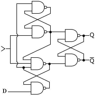
| D | > | Q | Q |
|---|---|---|---|
| 0 | 0 | ||
| 0 | 1 | ||
| 1 | 0 | ||
| 1 | 1 | ||
| 0 | |||
| 0 | |||
| 1 | |||
| 1 |
(Note: You may find it helpful to extend the truth table to describe what is happening. In other words, treat Q and Q as inputs as well as outputs.)
activate? Is it when the > is 0? 1? Changes from 0 to 1? From 1 to 0?
For this assignment, paper submission is easiest. However, you may also submit electronic copy through WebCT if you are concerned about the possible loss of paper, want a record of turning it in, etc. Pdf is the safest format for capturing non-text, please check with the TA for formats other than html, text, or pdf. Hard copy is acceptable, please hand in at the beginning of class.